About this site
This site aims to provide radio amateurs with easy-to-use tools to help them design simple, light but effective wire antennas which are especially suitable for portable use while participating in any of the several amateur radio outdoor award schemes.
Antenna types
Currently, the site offers tools to help the user design these different types of antenna:
- Linked dipole antennas - inverted-vee wire antennas for up to six bands
-
OCFD antennas
- wire dipole antennas fed off-center, set up as a half-wave inverted-V, and built for one principal band but, depending on
how the antenna is configured, can be usable on up to four higher amateur bands -
EFHW antennas
- wire antennas fed at one end, set up as a half-wave inverted-L or inverted-V, built for one principal band, but usable on
several higher amateur bands -
Vertical antennas
- wire antennas built for a single band, set vertically, often 1/4 wavelength, and with a number of radial elements to provide
an electrical ground - currently in BETA version - Delta loop antennas - wire antennas built for one band only, but well suited to DX work
- Half-square antennas - wire antennas which can be configured either as current-fed full-wave single-banders, or as voltage-fed EFHW multi-banders
- Moxon antennas - wire or tube compact 2-element beam antennas with good forward gain and very good front-to-back F/B ratio
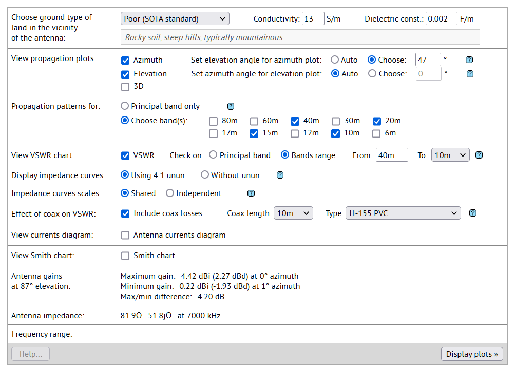
The site also offers a collection of charts, tables and calculators in the Extras page:
- Extras page - a collection of data representations and calculators
Notes
- Use the contact form below in this page to send a message to us at portable-antennas.com .
- Disclaimer - please read carefully.
About the designers
Each of the designers listed here share a common structure and form, while presenting combinations of controls specific to the type of antenna covered.
In each case, the user is presented with a group of controls in the upper left portion of the page: these controls enable the user to completely specify the characteristics of the antenna, namely frequency, wire lengths, angles, and so on. Please note that all length dimensions are given, or calculated, in meters.
In the upper right portion of the page is a graphics area where the modelled antenna is presented in a 3D context. The graphic can be zoomed, panned and rotated. Antenna feed-points are shown as colored markers; the user may also choose to toggle the appearance of a semi-transparent plane at the height (1.85 meters) of an average person, in order to gain some perspective on how large the antenna would be when erected.
In the lower half of each of the designers, a group of controls enable the calculation of an antenna's performance, and the presentation of charts and diagrams showing the performance in various ways, in any combination of the following:
- azimuth, elevation and 3D radiation charts
- VSWR charts, incorporating Real- and Imaginary-reactance curves
- an antenna currents diagram
- a Smith chart
Calculation of an antenna's performance is achieved using a version of the NEC2 (Numerical Electromagnetics Code v.2) code. Results of the calculations, and the resulting charts and diagrams, have been compared with those presented by programs such as EZNec and 4nec2, for similar antennas, and have been found to be closely comparable. Notwithstanding that, we make NO claims as to the accuracy of such information or results; the graphics and data presented in this site are provided "as-is" for the general interest and edification of the user. Refer to the Disclaimer below for more information.
Linked dipole designer
The linked dipole antenna designer page enables the user to very quickly design a multi-band linked dipole antenna for portable use in the field, or on a mountain top.
This type of antenna is constructed with one or more sections in series, each for a particular amateur radio band, and which are capable of being linked, or unlinked, as required, to make the antenna resonant on whichever band the radio operator wishes to use. Linking or unlinking sections has, however, the downside of having to lower the antenna to physically reach the very highest links.
Linked dipole antennas are especially easy to erect, requiring just one support in the center - this could be a pole or a cord suspended from a tree - amd have the added benefit of giving good results even when erected in thick forest, since the antenna radiates horizontally polarized, while the trees present little obstacle since they are not only physically, but also electrically vertical. So the trees have little influence on the radiated signals - good for heavily-forested hills amd mountain summits.
OCFD antenna designer
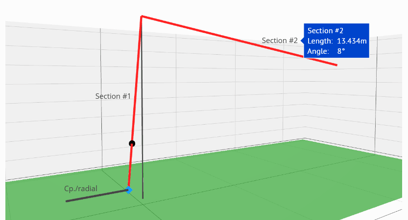
The OCFD antenna designer page enables the user to quickly design a multi-band OCFD (off-center-fed dipole) antenna for portable use in the field, or on a mountain top. OCFD antennas consist basically of two wires, together comprising one half-wavelength in length, and fed in a similar manner to a center-fed dipole, but fed off-center at a point usually about 1/3 in length from the end; the designer, however, allows the feed-point position to be configured for optimal performance for those bands of interest to the operator.
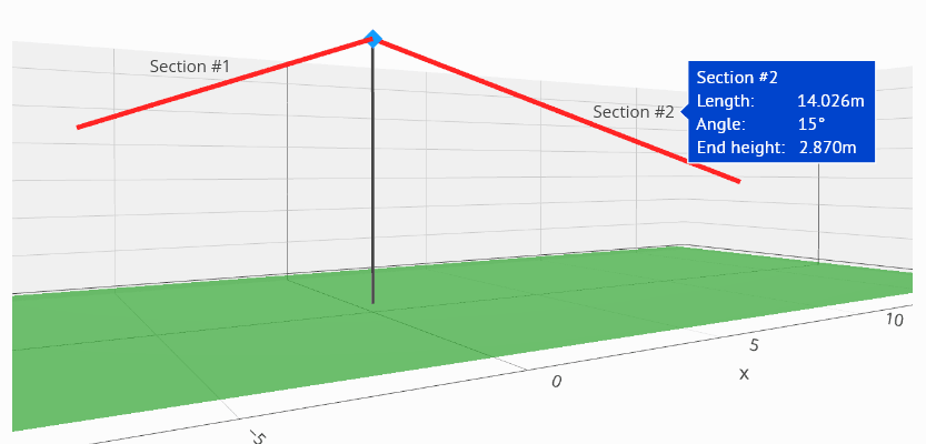
The OCFD antenna is often stated to present an impedance of around 200 ohms to 250 ohms at the feed-point, and is often fed through an unun, usually 4:1, to match a 50-ohm system. A current choke is often also needed to suppress common-mode currents on the feed-line. However, the actual impedance values of a particular OCFD antenna configuration will most often be quite different, and will vary with:
- the relative antenna section lengths (i.e. as in the most-often used 33% / 67% OCFD),
- the height of the antenna above ground,
- the angles to horizontal of the antenna sections.
Actual values for the impedance at the antenna base frequency can vary between 73 ohms to several hundred ohms, depending on the configuration (refer to the 4th column in the table below).
One big advantage of the OCFD antenna, as compared to a center-fed dipole, is that it can exhibit low VSWR minima on two, three or four higher bands above the principal band for which it has been designed: for example, with a judicious choice of feed-point position, a 40-meter OCFD can resonate also on the 20-meter, 15-meter and 10-meter bands, with the 6-meter band being an added possibility.
The performance of an OCFD antenna is very sensitive to the choice of feed-point position, as the table below demonstrates. This table lists VSWR values at the stated frequencies across several bands for a 40-meter OCFD, principal frequency 7.000 MHz, erected as a flat-top at 10 meters above average ground. VSWR values for the stated frequencies in each band are displayed as a function of the percentage split between the two separate sections of the antenna, here listed as "Left" and "Right":
| Split | Ratio, R/L |
Feed-point impedance at 7.1 MHz |
Band | Bands* | |||||||
|---|---|---|---|---|---|---|---|---|---|---|---|
| Left % |
Right % |
40m (7.1 MHz) |
30m (10.1 MHz) |
20m (14.2 MHz) |
17m (18.1 MHz) |
15m (21.2 MHz) |
12m (24.9 MHz) |
10m (28.5 MHz) |
|||
The animation below uses the same antenna configurations as the table, and demonstrates graphically how sensitive an OCFD antenna is to the relative ratios of the two sections, left and right:
| 40-meter OCFD antenna |
From these data, it can be seen that the most often-used 1/3 to 2/3 (or 33% / 67%) ratio section lengths used for a 40-meter OCFD antenna will result in the antenna being resonant on three amateur bands, 40m, 20m and 10m, but NOT on 15m. In order to get a 40-meter OCFD antenna to be resonant also on the 15m band, a different lengths ratio between the antenna sections must be used.
Among the best ratios to be used, as both the graphic and the table show, are close to an 18% / 82% or 20% / 80% ratio which gives good
VSWR minima on all four bands 40m, 20m, 15m and 10m. This is also borne out by the comments made in Part 4 of this document on OCFD antennas:
https://rsars.files.wordpress.com/2013/01/study-of-the-ocf-dipole-antenna-g8ode-iss-1-31.pdf
where the author suggests a 1/6 to 5/6 (or 16.67% / 83.33%) ratio would be the best choice to bring the antenna to resonate on four HF bands
40m, 20m, 15m and 10m, and incidentally also on the 6-meter band.
Changing the angles (within reasonable limits) of the two arms of an OCFD antenna has a much less profound effect on VSWR and bands coverage than the choice of feed-point position. Angling one or both arms downward, however, has the effect of lowering the antenna impedance somewhat.
The OCFD antenna can be a very useful and time-saving field antenna in the field - simply change TRX band to one of the antenna's resonant bands, and start transmitting.
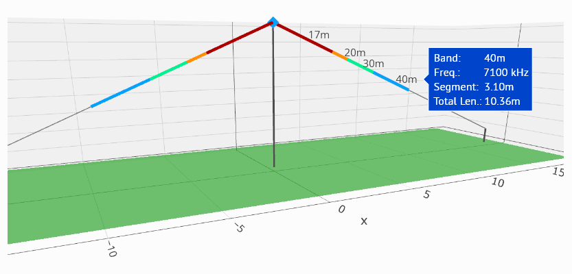
EFHW antenna designer
The EFHW antenna designer page enables the user to quickly design a multi-band EFHW (end-fed half-wave) antenna for portable use in the field, or on a mountain top. EFHW antennas consist basically of one single wire, a half-wavelength in length, which can be configured in several ways:
- as an inverted-L antenna
- as an inverted-V antenna
- as a vertical antenna
Being end-fed, the EFHW is voltage-fed and presents a high impedance (around 2500 ohms to 3500 ohms) at the feed-point, and hence needs an unun, typically 49:1, to match a 50-ohm system.
One big advantage of the EFHW antenna is that it can exhibit low VSWR minima on several bands above the principal band for which it has been designed: for example, a 40-meter EFHW can resonate also on the 20-meter, 15-meter and 10-meter bands, with 6-meters being thrown in for good measure. This can readily be seen in the diagram below:

Careful optimization of the EFHW antenna characteristics is needed to ensure good performance in the field. Ground conductivity plays a part, as well as choice of principal frequency, configuration, and inductive/capacitive loading of the antenna. If done right the EFHW antenna can be a very useful and time-saving field antenna - simply change TRX band to one of the antenna's resonant bands, and start transmitting.
Vertical antenna designer
The Vertical antenna designer page enables the user to quickly design a single-band vertical antenna for portable use in the field, or on a mountain top. The vertical antenna designer page is currently in BETA version...
For portable use, the vertical antenna is most often constructed of wire, supported by a pole of sufficient height to accommodate the complete antenna length. If the vertical section is - as is commonly the case - 1/4λ in length, a number of radials are needed to complete the antenna.
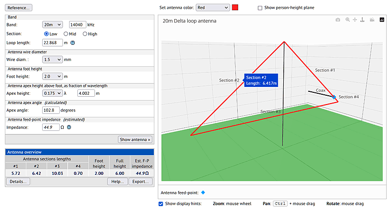
Delta loop antenna designer
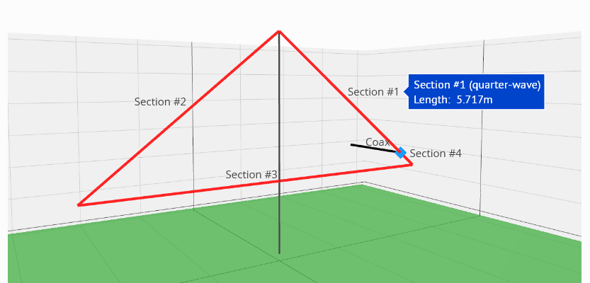
The delta loop designer page enables the user to quickly design a single-band vertically-polarized delta loop antenna for portable use in the field, or on a mountain top. It needs just one support, a pole or cord suspended from a tree.
This type of antenna is constructed as a closed triangular loop, with the apex at the top, and is designed for one particular amateur radio band. It is fed on one of the sides, close to a lower corner: the coax center conductor is connected at a point 1/4 wavelength down from the apex, and the coax shield is connected to the short part of the same side: in this way it propagates predominantly vertically-polarized waves.
The delta-loop antenna generally features a low vertical take-off angle, even though such antennas are erected with their lower side only a couple of meters above the ground. The low take-off angle makes this kind of antenna a worthwhile prospect for DX-ing, especially while operating portable. If erected on a summit where the ground drops away appreciably from the summit, the take-off angle will be even lower; placing the delta-loop antenna higher up on its' center support will also lower the take-off angle.
Another feature of the delta-loop azimuthal radiation is the very deep low at high elevation angles (see the diagram below), meaning much less power is dissipated at high angles. This means, however, that this antenna is not a good choice for NVIS communications.
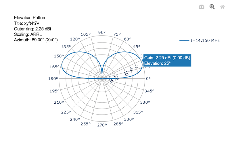
The delta-loop antenna is also fairly broadband on its' designated band - the 2.0:1 VSWR range on the 20-meter band for example, at ~350kHz wide, covers the entire band.
Two slight disadvantages can be encountered when erecting the delta-loop antenna:
-
it requires a little more effort to erect than a simple, or linked, dipole, since it's often the case that one of the center-support
guy-lines
needs to be "threaded" through the loop - with a little practice, however, this is easily accomplished; -
the coax feed-line needs to be carefully led away from the antenna at 90° for a couple of meters, in order to minimize common-
mode
currents on the coax sheath.
One should also note that the center of the antenna's horizontal side (its' "foot") is a voltage high-point, which is why the antenna should be erected high enough (2 meters minimum) that neither the operator nor a casual passer-by can easily come into contact with that point.
Half-square antenna designer
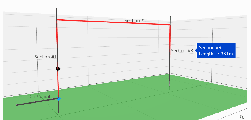
The half-square antenna designer page enables the user to quickly design a half-square antenna for portable use in the field, or on a mountain top. This type of antenna needs two supports: a combination of pole(s) and/or cord(s) suspended from a tree. Half-square antennas can be configured in one of two ways:
- when fed from one of the top corners, it functions as a full-wave single-bander
- when fed from one of the ends, it functions as an EFHW half-wave multi-bander
Half-square antenna configured as a full-wave single-bander
When configured as a full-wave single-bander, the impedance at the upper corner feed-point is approximately 50 ohms, and hence does not necessarily need an unun at the feed-point, although a 1:1 unun is often used. It's important to run the coax feed-line at 90° to the antenna for a couple of meters in order to minimize common-mode currents on the coax sheath.
This configuration results in a fairly low angle (~ 20° to 25°) elevation radiation pattern, with good broadside lobes, deep (typically better than 12dB) rejection in the plane of the antenna, and a deep (~15dB) minimum at high elevation angles. This makes this configuration a good choice for single-band DX work.
Half-square antenna configured as an EFHW half-wave multi-bander
When configured as a half-wave multi-bander, the impedance at the end of the wire is around 2500 ohms to 3500 ohms, and hence an unun, typically 49:1, is needed at the feed-point. In addition, the antenna will also most often need a short (~1/8 wavelength) counterpoise.
Like other EFHW antennas, this configuration can exhibit low VSWR minima on several bands above the principal band for which it has been designed: for example, a 40-meter half-square configured in this way can resonate also on the 20-meter, 15-meter and 10-meter bands, with 6-meters being thrown in for good measure.
Moxon antenna designer
The Moxon antenna designer page enables the user to quickly design a Moxon 2-element beam antenna for portable use in the field, or on a mountain top. This type of antenna needs a single support only.
First designed in the early 1950's, and later further developed by L.B.Cebik in the 1980's, the Moxon antenna has become a firm favourite for those interested in building a lightweight beam antenna for home or portable use.
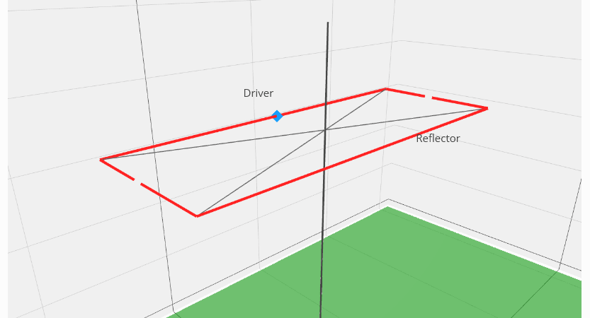
Since the Moxon is a beam antenna consisting of a driver element and a single parasitic reflector element, both folded toward each other, it makes for a usefully compact array. It can be made of wire supported by spreaders, or from lightweight tube which is mostly self-supporting. In both cases, however, a single support only is needed, which is very handy when erecting the antenna for portable operations.
Like other beam-type antennas, the Moxon can be configured either as a horizontal beam, or as a vertical beam, with the radiation polarized as the configuration. In both configurations, as with all 2-element driver-reflector beams, the gain is highest at the low end of the band and tapers off as the frequency is increased. See the following sections for more information...
Moxon antenna configured as a horizontal beam
The horizontal Moxon beam offers a broad forward azimuthal radiation lobe giving modest directivity of about 2dB, with a deep null toward the back end, giving a high front-to-back ratio: gains of up to 9.7dBi are possible. The azimuthal radiation pattern is only moderately sensitive to the height of the antenna above ground, whereas the shape of the elevation pattern depends very strongly on the height of the antenna above ground. The following animation shows both azimuth and elevation patterns for a horizontal 10-meter Moxon beam at heights between 4m and 10m above ground level (height measured at the antenna center):
| Horizontal Moxon |
As can be seen from the graphic, at lower heights of 4m or 5m AGL, the elevation pattern consist of a single lobe with elevation angle of around 25° to 35°. At greater heights AGL, the elevation pattern splits into two very distinct lobes, one low and one high, such that the signal is "shared" between them - this can be useful for both long-distance DX contacts, as well as for more close-in contacts.
Moxon antenna configured as a vertical beam
The vertical Moxon beam offers a very broad forward cardioid azimuthal radiation lobe giving modest directivity, with a deep null toward the back end, giving a high front-to-back ratio. Both the front-to-back ratio and the SWR depart from optimal values more rapidly below the design frequency than above it. Hence, the design frequency will normally be about 1/3 the way up the overall operating passband.
The azimuthal radiation pattern exhibited by the vertical Moxon beam is only moderately sensitive to the height of the antenna above ground, whereas the shape of the elevation pattern again depends very strongly on the height of the antenna above ground.
The following animation shows both azimuth and elevation patterns for a vertical 10-meter Moxon beam at heights between 1m and 8m above ground level (height measured at the lowest part of the antenna):
| Vertical Moxon |
As with the horizontally-oriented Moxon, the elevation pattern at different heights AGL also shows a second elevation lobe above the main lobe, but at shallower angles than with the horizontally-oriented Moxon. At lower heights of 1m or 2m AGL (measured at the lowest part of the vertically-oriented antenna), the elevation pattern mainly consists of a single lobe with elevation angle of around 15°.
At greater heights AGL, the elevation pattern splits into two lobes, one at low elevation and one at a somewhat higher elevation, such that the signal is "shared" between them, but in this case, the two elevation pattern lobes are much closer together than is the case with the horizontally-oriented Moxon, and present more of a low- to mid-angle "broad front", serving both DX and middle-distance contacts.
Moxon antenna VSWR curve
The Moxon antenna has a very distinctive VSWR curve, the shape of which is only weakly dependent on orientation and/or height AGL:

The curve displays a steep rise at frequencies below the VSWR minimum, and a more shallow rise at frequencies above the VSWR minimum.
In all cases, and using the calculated dimensions, the feed-point impedance stays close to 50 Ω, the VSWR is low (2.5 or less)
and bandwidth is high - even across such wide bands as 10 meters, 6 meters and 2 meters.
Extras page
The extras page offers the following in separate tab-pages:
-
a list of coaxial cables suitable for portable use:
- for each cable type, a breakdown of its' main characteristics
- for each cable type, a chart showing the attenuation, in dB per 100 meters, by frequency
- two cables can be compared side-by-side in the chart of cable attenuation by frequency
- a calculator is also provided to enable the user to convert attenuation values in dB to percentage loss
- charts and tables detailing reference correction factors used in the designer pages
- charts of insulation correction factors by insulator type and wire diameter
- a frequency-to-wavelength calculator
More tools are planned for this page.
Contact form
- Seen something in this site which doesn't work? - let us know!
- Have suggestions for site improvements? - we'd love to hear them!
- Just want to tell us how much you like the site? - we're all ears!
- Don't like this site, or what it has to offer? - we won't hold it against you!
| Your name: | |
| Your email address: | |
|
Your message:
(Plain text only please) |
You have 1000 characters left
|
| For humans only: | |
|
|
|
Acknowledgments
The software used in this site to generate antenna radiation plots data, and also the plots themselves, is open source and freely available (except where noted) for non-commercial use:
- C-based NEC v2 radiation plots data generator: nec2c at https://github.com/cvvs/nec2c
-
NEW NEC v4.2 radiation plots data generator: under license from Lawrence Livermore National Laboratory
at https://softwarelicensing.llnl.gov/product/nec-v42 - Python-based radiation plots generator: plot-antenna at https://github.com/schlatterbeck/plot-antenna
- Python-based graphing library: plotly at https://github.com/plotly/plotly.py
- Javascript-based 3D charting library: Plotly.js 3D Charts at https://plotly.com/javascript/3d-charts/
-
Javascript- and SVG-based charting libraries: highcharts at
https://www.highcharts.com/
- as a non-profit organization, we may use the highcharts libraries without a license.
We are grateful for the opportunity to use all of these resources, and acknowledge our debt of gratitude to their respective developers.
Please note: due to the reliance on sizeable graphics and groups of controls in this site, it is not suited to display on small screens. We apologize for any inconvenience this may cause.
Disclaimer
All information on this web site is provided "as is", for general information purposes only, to the amateur radio community and those with an interest in radio technical matters.
The operator of this web site makes no representations or warranties of any kind, express or implied, about the content, completeness, accuracy, reliability, legality, suitability or availability, with respect to the website or the information, products, services, or related graphics contained on the website, for any purpose. Any reliance you place on such information is therefore strictly at your own risk.